Making clocks(These notes are adapted from my article published in Practical Woodworking in December 1991. They are provided as guidance for making the clocks shown in the gallery. The types of clock presented are: one pedestal clock and five free-form clocks.)General introductionMovementsQuite a number of people in the UK supply movements but prices can cover a wide range for the same item. Most of them are reliable; if there is a fault it often occurs in the first few minutes of use because of a foreign body in the works. It is usually cheaper to buy in quantities. If you belong to a local wood turners association maybe you can get together and make a group purchase. Whatever you do, shop around amongst the suppliers who advertise in magazine or catalogues.Marking the divisions on the clock faceYou can use your ingenuity to think of ways of marking the divisions on the clock face. My favourite method is to drill shallow holes to mark the hours. I have also used brass plated gimp pins.The Pedestal Clock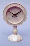
IntroductionThe drawing provides some suggestions for the dimensions. The wood used for the pedestal clock shown here was ash but almost any hard wood could be used satisfactorily. The clock is made up of three parts: the head, the stem and the base.The headTo make the head a circular blank is mounted on a screw chuck and the face turned. The recess for the hands is made a suitable size to fit onto the expanding jaws of a chuck. For appearances sake the inside corner of the recess should be almost square. The jaws will hold it firmly with only a very small amount of under-cut.After the face has been completely turned and finished it is reversed on the chuck. The hole for the movement spindle is then drilled, and the back, including the recess, is turned. The right amount of material must be left between the recesses on the front and the back of the work-piece so that the movement can be fixed in place correctly. It is possible to measure the thickness of the wood through the spindle hole. The baseThe base is turned on a small screw chuck. When it is finished a 1/4in diameter hole is drilled in the centre of the topThe stemThe assembly is held together by 1/4in diameter dowel. One way to ensure that the hole is central in the stem of the clock is to drill the blank all the way through before it is turned. It can be held in the lathe either on a mandrel or, my method, between cone centres. If the latter method is employed a revolving centre must be used in the tailstock to reduce the friction at that end. If that is done then the cone centre in the headstock will provide an adequate drive.AssemblyBefore the pieces are assembled a hole has to be drilled in the bottom edge of the face. To do this the face is clamped to an L shaped jig to keep it vertical on the drill press and is carried out in the same way as drilling the head of a mirror, as described in the mirror project. A designers kit of partsIf you are unsure about the way the pieces will look when they are assembled, or if you wish to try out different designs, then you can make yourself a designers kit of parts. Such a kit is shown in the photograph. If the jointing dowels are glued (only) into the stem sections then the pieces can be fitted together, temporarily, in a variety of ways.Free-form clocks
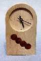
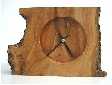
IntroductionThe turning procedures described for the free-form clocks (shown above) in the next few paragraphs are dangerous and any carelessness or lack of concentration could result in serious damage to the hands. Because of this these procedures should only be undertaken by more advanced turners. The danger lies in the fact that these pieces are not round and will be spinning like propeller. The turning itself is not particularly difficult but anyone who is having to concentrate hard on the turning techniques may forget that the way some of the pieces are held is dangerous. So do be careful. It might be a good idea to lock the workshop door at critical times, so that you will not be disturbed. If anything should interrupt you, stop the machine immediately, and do not start again until you are ready to concentrate once more. It should be noted that there is a much safer way making these clocks which is described in the final section of this project. This being the case you may well wonder why I am spending time on this section of the project. The fact is that making special jigs takes time. So when I am making free-form clocks of a very irregular shape, such as the apple and the yew clock shown here, I turn them without a jig in the way I am describing in this section. All the clocks shown above were made in this way. However, since making the first of the ash clocks I have made a number in the same style and I now have a jig for these, as described in then final section. Making the free-form clocksSeveral different shapes are shown in the photos; if you do not like my shapes then you can, of course, dream up some of your own. The sizes of the clocks shown in the photos are as follows: the ash clock (with yew inserts) is 8in by 4 1/2in by 1 1/4in, the teak clock is 6 1/2in by 4 7/8in by 1in, the apple and yew clocks are 5 inches and 6.5 inches high respectively. The shape is cut on the band saw and the edges are sanded smooth on a belt or disc sander. The faces are then planed and sanded. The lathe is used only to cut a circular recess on each side. A router could be used for this but that would require special jigs and templates - hardly worth while for a small number of different sized items. The work-piece is turned, first, on a screw chuck and then on expanding collets. As the two recesses are not central the work-piece will be out of balance. If the clock is small in relation to the lathe then no special measures need be taken to balance the work-piece as long as a slow speed is selected. For example I turned the smaller of the two teak clocks over the bed on my Coronet Major on the next to bottom speed (about 800 rpm). The ash clock and the larger teak clock I turned over the bed of my Poolewood Superlathe at a relatively low speed. If it is found that the unbalanced clock blank shakes the lathe too much then it can be treated in the same way as the oak clock. This required special measures that are described below. There is another possible solution to the problem of imbalance. If some wastage of wood is acceptable (or if off-cuts can be used for some other project), the recesses could be turned in the middle of a rectangular piece of wood that would be cut to shape later. Forming the recess for the faceThe recess that forms the face is formed with a small bowl gouge and scrapers. A skew scraper is handy for getting into the square corner. I make the recess 3 1/2 in. in diameter. It will be found that expanding jaws will hold the work piece securely with a very small amount of undercut in the recess. Forming the recess for the clock movementWhen forming the recess on the back of the clock it will be necessary to ensure that the right thickness of wood is left for the fitting of the movement. The thickness required will of course depend on the fittings supplied. For the movements and fittings which I used it was 1/4in. If the hole used for holding the work piece on the screw chuck is opened out for the clock movement spindle the thickness of wood remaining can be measured through the hole. (For the movements I have used the diameter of the hole for the spindle 3/8 in., or thereabouts.) The alternative method is to calculate the depth of the recess for the movement by measuring the depth of the recess for the hands (before fitting it onto the expanding collets) and the thickness of the work piece.The Oak clock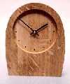
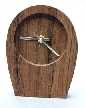
The oak clock,shown on the right, (which I made some years ago) is 8in by 6 5/8in by 1 3/8in. As such it was too big to turn by the methods described above. As I mentioned earlier this type of free-form clock could be made by turning the recesses in the middle of a large piece of wood and cutting the piece to shape later. However, not only would this be wasteful but the recess for the face will probably be too big for the piece to be held directly on a chuck. Raises the question of how it will be held on the lathe. As it happens the solution to this problem also provides a ready means to balance the piece. The procedure is as follows. Band saw the clock blank to shape, clean it up and sand the edges. Drill a 3/8 diameter hole where the clock spindle will be located. Take a large piece of scrap chipboard, thick plywood or MDF, and cut it to a circle - for the clock shown this was about 13in diameter. Mount this disc on a faceplate and fit the assembly on the lathe; then drill a 3/8in hole in the centre. Remove the assembly from the lathe and glue a short piece of 3/8in diameter dowel in the hole. This is used to locate the work piece. The disc now needs to be made into a crude four-jaw chuck with the aid of four small L shaped wooden clamps. These are screwed into place to hold the work-piece securely against the disc. Then the whole arrangement is balanced with some lead weights that are bolted on to the disc towards the rim. If the assembly work has been carried out in an intelligent manner there will be no danger in anything coming adrift but, as high speeds are not required for the turning, it is as well to keep the speed down, and thus the centrifugal forces, to a minimum. However, once again I must stress the danger of getting the fingers caught. (The photographs show the assembly on the lathe and in use.) A safer way of making free-form clocksThe method I used for making the oak clock described above led me to the way to make the process safer. The idea is to clamp the clock blank to the backplate with a circular disk. (This is shown in the photographs.)There are a number of points to note. The backplate is balanced with lead weights and has a dowel in the centre, as for the oak clock. Two strips of wood are fixed to the backplate close to the position for the clock blank. These prevent the clock blank revolving when it is turned and help to keep the clamping disk in the correct position. The clamping disk must be tightened down securely by the two bolts to ensure that the clock blank will not slip off the central pin and be thrown out of the jig. (This happened to me once, fortunately I was not standing in the firing line.) As an extra precaution a small stop bracket can be fastened to the backplate at the bottom of the clock blank. I have done this on another jig which I use. |

© Brian Clifford (September 2001)