INTRODUCTION TO WOODTURNING
Chapter 7: The effect of grain and other factors on the cut
7.1 Introduction
In the previous chapter, in thinking about the way the tool cuts, three important factors were temporarily ignored. These are :
- the question of grain and its direction
- the rotation of the work-piece
- the fact that the cutting edge is often held at an angle to the direction in which the wood is moving (the slicing cut)
7.2 The concept of grain
The cells of the wood, which take the form of hollow cylinders, join together to form strands of fibres which lie in a uniform direction which is more or less axial either to the trunk or to its offshoots. The lay of the fibres is commonly referred to as the 'grain'.
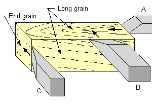
Diagram 7.1 Primary forms of cut
Diagram 7.1 shows a block of wood in which the grain is running longitudinally. Three tools are shown as if about to make cuts in the directions indicated by the arrows. These illustrate the three primary forms of cut; as defined in the common expressions of:
- cutting along the grain (A);
- cutting across the grain (B);
- cutting end grain (C).
In practice of course, particularly in woodturning, there is an infinite range of variations on these cuts. Not only can any number of intermediate positions between those shown be taken up but the edge of the tool does not necessarily have to be held at 90 degrees to the direction in which the wood is moving.
It should be noted that in Diagram 7.1 the wood is assumed to be stationary and the tool to be moving. Often, in woodturning both the wood and the tool are moving, but with the wood moving faster than the tool. For the purposes of analysis, in this particular context, this does not matter; all that we are concerned with here is the movement of the wood and the cutting edge in relation to each other.
7.3 Cutting along the grain
Anybody who has worked wood with a hand plane will know that it is desirable to plane with the grain. Diagram 7.2 illustrates the common situation in which the fibres of the wood lie at an angle to the edges of the wood block.
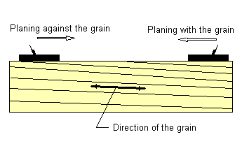
Diagram 7.2 Planing with and against the grain
When the wood is planed with the grain any splitting between the fibres takes place above and in front of the cutting edge, which subsequently severs the fibres neatly, so leaving a clean surface, as shown in Diagram 7.3.
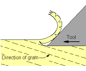
Diagram 7.3 Cutting with the grain
Based on: Bruce Hoadley, Understanding Wood, The Taunton Press (1980) - p150
If an attempt is made to plane against the grain the cutting edge picks up the ends of the fibres, lifting them out of the wood, so that they break off in an irregular manner leaving a rough finish. This is illustrated in Diagram 7.4.
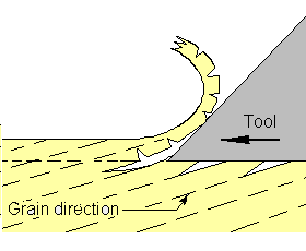
Diagram 7.4 Cutting against the grain
Based on: Bruce Hoadley, Understanding Wood, The Taunton Press (1980) - p150
7.4 Cutting end grain
When an attempt is made to cut end grain the cutting edge is forced across the ends of the fibres and there is a danger that they will be disturbed below the cut surface before they are severed (see Diagram 7.5). If the tool is allowed to pass beyond the edge of the work-piece, where the fibres have no support, a piece of wood may splinter off. When cutting end grain fine cuts need to be taken to minimise this problem.
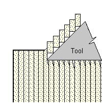
Diagram 7.5 Cutting end grain
Based on: Bruce Hoadley, Understanding Wood, The Taunton Press (1980) - p155
7.5 Cutting across the grain
When cutting across the grain the wood fibres will lie parallel to the edge of the tool. As the tool penetrates the wood the fibres do not always separate cleanly in front of the edge of the tool (as illustrated in Diagram 7.6). Some of the fibres may be lifted out of the surface below the cutting edge leaving a series of parallel furrows. This affect can often be easy to see; one instance is when a parting tool has been used to cut a groove.
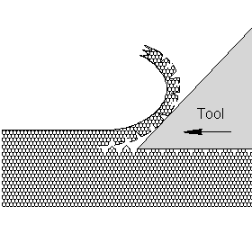
Diagram 7.6 Cutting across the grain
7.6 The way the work is held on the lathe and the terminology
The different ways in which the work piece can be held on the lathe affect the way the grain runs and have important implications for consideration of the way in which the wood is cut.
There are three main ways of holding the work-piece in the lathe:
- between a drive spur in the headstock and a centre in the tailstock
- by one end only
- by one face only
The first of these two is commonly referred to as turning 'between centres'. The term 'spindle turning' also refers to 'between centres' work but usually in relation to a relatively slender work-piece such as a chair leg or a lamp column. Generally, however, these terms are interchangeable. It should be noted that the techniques used in spindle turning can, and frequently are, applied to a work-piece held by one end only. The stem of a goblet is a good example.
Bowl turning is usually carried out with the work piece held on one side only; nevertheless it is possible for some, if not all, of the operations to be carried out with the bowl-blank held between centres. Also, although bowls are usually made from a work-piece in which the grain is orientated at right angles to the axis of the lathe they can also be made from a piece in which the grain runs parallel to the axis. We need to use some terminology which will cover all the combinations which these possibilities allow.
When the inside of a bowl, a goblet, or any similar object, is hollowed out with the work-piece held by one end, or one side, and with the grain parallel to the axis of the lathe, this is commonly referred to as 'end grain turning'. As far as I am aware there is no common term applied to the same operation carried out where the grain is at right angles to the axis (ie on a 'normal' bowl). The term I apply to this is 'face turning'. If any of the operations on a bowl are carried out between centres then these would be described by that term, that is as work carried out 'between centres'.
7.7 The implications of rotation
If we look at a cylindrical work-piece held between centres in the lathe we may, for example, see the grain running through it at an angle as shown in the piece of wood illustrated in Diagram 7.2. Then if we rotate the work-piece half-a-turn (ie 180 degrees) the grain will, in effect, be running in the opposite direction. Thus, when turning a cylinder, the grain, as it is encountered by the cutting edge of the tool will continually be changing its direction. Whether the tool is moved from left to right, or from right to left, the cut will alternately be made with and against the grain.
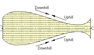
Diagram 7.7 Uphill and down hill - between centres
As soon as any shaping of the work piece takes place, however, the situation changes. Consider the vase shape shown in Diagram 7.7; for convenience, in this case, it is assumed that the grain is running parallel to the axis of the lathe. Cuts made in the direction marked 'downhill' will invariably be made with the grain and those marked 'uphill' against the grain. The terms 'uphill' and 'downhill' have been used because they have become part of the Woodturner's vocabulary. In this context, however, the terms 'up' and 'down' do not necessarily refer to tool movements related to the centre of the earth but to their relation to the work-piece. Thus a cut made downhill, ie with the grain, on a spindle turning is one made towards the central axis of the turning.
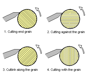
Diagram 7.8 Uphill and downhill - cutting on the rim of a bowl
When a face turning, such as a bowl is considered the situation changes. This is illustrated in Diagram 7.8, where the grain is assumed to run at a right angle to the axis of the lathe. The arrows show that when a cut is made around the rim of a disk the grain direction is continually changing, eg (1) end grain, (2) against the grain, (3) along the grain, (4) with the grain.
When the bowl shape is being formed the question of uphill or down re-emerges as shown in Diagram 7.9. Whether a cut is made uphill or downhill depends on the direction of the slope of the surface on which it is made (in relation to the axis of the lathe) and whether it is made on an inside or outside curve.
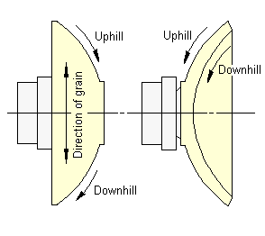
Diagram 7.9 uphill and downhill - shaping a bowl
Similar consideration apply to an end grain turning, such as a goblet. A cut made towards the axis on the inside of the cup will be uphill, ie against the grain. A cut made on the outside of the cup, also towards the axis will be downhill, ie with the grain.
At some point, when a bowl with a well rounded shape is being turned, the effects shown in Diagram 7.9 may be outweighed by those shown in Diagram 7.8, and when the gouge is encountering end grain it may begin to pick up the fibres of the wood. Even for experienced bowl turners this can create a problem. We will look at some methods which can be used to minimise the tearing of end grain on bowls when bowl turning is considered in detail in a later chapter.
7.8 The slicing cut
In Diagram 7.10 shows a work-piece held between centres with the grain running parallel to the axis of the lathe. Two square nosed chisels, A and B, are shown positioned with their bevels in the rubbing position. It is convenient, but not important, to assume the chisels to be square nosed, but B could, in fact, be skewed. What is important is that it is assumed that the edge of chisel A is held parallel to the axis whereas that of B is held at an angle. Unless chisel A is narrow, like a parting tool, it will be very difficult, if not dangerous, to hold in that position. The reason for this is that not only will the cutting edge be in contact with the wood along its full length, it will also be parallel to the fibres of the wood; ie it will be cutting across the grain. Since both ends of the edge will be below the surface of the wood the fibres will have to be torn away at these extremities. Even if the cut can be maintained the surface left will tend to be very rough.
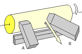
Diagram 7.10 The slicing cut
The case of chisel B is very different. Because it is held obliquely to a curved surface only small portion of its edge is in contact with the wood and so it will take a relatively narrow shaving. It should also be noted that the fibres at the edges of the shaving are severed by the tool.
There is yet another factor to be considered. The direction in which the shaving is travelling is shown by the arrow in Diagram 7.10 B. It can be seen that the edge of the tool is at an oblique angle to the direction in which the shaving is travelling. This means that the wood fibres are moving along the cutting edge so producing a slicing cut. The fibres are very fine and if they and the edge of a sharp tool were greatly magnified (on a similar scale), the tool would be seen to have a jagged edge like that of a saw. The saw-like action severs the fibres still more cleanly.
In the instances I have been looking at in the above paragraphs the chisel has been positioned so that it has been cutting along the grain (ie parallel to the grain). It should be noted, however, that the slicing effect is enhanced when the cutting direction is downhill, ie when the cut is being made with the grain. When a slicing cut is combined with cutting with the grain the possibility of lifting the fibres out of the surface below the cutting edge is considerably reduced and very clean cuts are possible even on awkward material.
It should also be noted that cuts in which the edge of the tool is oblique to the direction in which the wood is moving, ie slicing cuts, can also be made with gouges in which ever circumstances they made be used, eg when cutting a cove or forming a bowl.
|