 Wind chimes Wind chimes
Introduction
Wind chimes are becoming increasingly popular pieces of garden furniture. Although such chimes are not a new idea, and can be made in a wide range of materials, there is a contemporary type which uses aluminium tubes for producing the sound. Unfortunately, some of these are very crude and even the best designs I have seen leave something to be desired. Since these chimes are usually based on a circular form they lend themselves to turning and I have developed some ideas which I hope will appeal to readers.
Having used a set of these in my own garden there are a number of general observations I would like to make before going into the details of how they are made. First and foremost: the sound needs to be much quieter than might be thought. What can be a very attractive tinkling sound in moderation can become irritating if it is too loud or too prolonged. I find the chimes work best in a light breeze; it follows from this that some means of silencing them needs to be provided when the wind freshens. In practice this can easily be achieved by catching the vane, or the striker, on the hook from which the chimes are suspended.
My own experiments suggest that the desired tinkling effect is best achieved by means of a fairly heavy striker and a very light vane. Also, the larger the diameter of the tube the more sonorous and attractive the sound. I would not use anything less than 1in diameter tube; this is what is used in the design shown here. However, if the design is scaled up, much larger tubes can be used to good effect. Another point is that a better sound is produced if the suspension point on the tubes is not at the very top but some distance down. The lengths of the tubes I used go from 14in to 20 7/8in in 1 3/8in. steps. Those who have greater musical skills than me may wish to try to tune the tubes to a suitable scale by adjusting their lengths. A drawing is provided for guidance. The design can be copied in detail or variations can be made to suit the whims of the maker.
The materials
Some comments on the materials used are also in order. The wood used for the turned parts, that is, the knob, the cap, and the striker, should be material which will weather well, such as elm or oak, and not Ash, which is unsuitable. However, a relatively dense piece of pine or, possibly, external grade plywood, could be used and painted if required. For the string retainer, which fits under the cap, and is merely a flat disc, I used oil tempered hardboard. If any other material is used it should be something which will stand up to the weather or which can be suitably treated. The vane should either be made out of thin sheet of wood, 1/8 in. maximum thickness, or from some other light material. Oil tempered hardboard will be all right; the rough side can be sanded smooth to improve the appearance.
To obtain the aluminium tube look up Aluminium Stockists in the Yellow Pages and ring around. I found one who was prepared to sell small quantities over its trade counter. The tube comes in long lengths; make sure the stockist will cut it, or take a hacksaw or a plumbers pipe cutting tool with you when you go to collect it. For the strings, with which the tubes, the striker and the vane are suspended, I used thin nylon cord (similar to that used on the bathroom light switch).
Turning the knob
Now we come to the turning. The knob is a relatively straight forward between-centres job, 1 1/4in in. diameter overall. Some care needs to be taken with the spigot which will eventually be glued into a hole drilled in the cap. It therefore needs to be cut to size with sufficient accuracy to provide a reasonable fit.
One way of cutting an accurate spigot is by careful use of callipers. A somewhat easier method is to use a sizing tool; it may be found necessary, however, to set the size on a trial piece.
The cap
The cap is a straightforward piece of face turning. It should be 6 7/8 in. in diameter and, about, 1 3/8 in. deep, when finished. Since it is going to be drilled in the centre with a 1/2 in. hole, to take the spigot on the knob, it can be held initially on any screw chuck the turner has to hand.
The bottom of the cap is turned first. It has a recess to take the string retainer (see below) and inside that a recess to accept the expanding collets of proprietary chuck. If the turner does not possess this type of chuck the piece can be reversed onto the screw chuck. In this case, of course, the recess for the collets can be omitted. Also on the bottom, just inside the perimeter, a groove is formed. This is intended to prevent rain water running across the string retainer, ie, like a drip moulding.
Turning the top of the cap should present no problems. If it is to be refitted on the screw chuck there may be a minor loss of concentricity. Should the latter be a cause of concern it can be disguised by the using a slightly different design (see drawing). Because this design eliminates the recess for collets and is a simpler shape it is also quicker and easier to make. Before the cap is finally removed from the lathe the 1/2 in. diameter hole to take the spigot on the knob is drilled. If a screw chuck is used it is better if the screw does not go right through the blank; in this case the hole for the spigot can be started whilst the piece is on the lathe. This will ensure it is positioned accurately on the drill press.
The striker
The striker, which is a simple shape, should be 1 1/4 in. deep and 3 in. in diameter when finished. I find it hangs best with a piece of 1/4 in. dowel running through it. The strings by which the striker and the vane are suspended are tied through holes in the end of this dowel. The hole for the dowel can be drilled in the blank for the striker before the piece is made. It can then be turned using a fixed cone centre in the headstock and a revolving cone centre in the tailstock. Alternatively it can be turned on a mandrel; this can be made with a short piece of 1/4 in. studding held in a Jacob's chuck. A small depression is punched. or drilled, in the centre of the face of the outer end to accept the point of a revolving centre. A couple of nuts will also be required to hold the workpiece in place.
The string retainer
As described above, the string retainer is a flat disc; it is 5 3/4 in. in diameter. It has 3 holes drilled in it for the screws which attach it to the cap; and 6 holes to take the strings which support the tubes. The latter holes are equally spaced on a pitch circle diameter of 5 1/8 in. A saw cut is made from the edge of the disc to each of these holes so that the strings can be looped across adjacent holes. A 1/2 in. hole is drilled in the centre for the spigot on the knob to pass through.
The tubes
The lengths of the tube are given above. Two 5/32 in. holes, diametrically opposed, are drilled in each tube 3 1/4 in. from the top end. Since 12 of these holes have to be drilled it is worth making a simple jig which can be clamped onto the table of the pillar drill. This jig has a short piece of wood with a 'v' cut into it to support the tube and a stop which ensures that all the hole are drilled at the same distance from the end of the tubes.
The strings
The strings (nylon cord) are tied in such a way that the knot is hidden inside the tube. This is done by threading one end of a piece of cord into one hole, and the other end into the opposite hole (from the outside in both cases). The ends of the cord, being inside the tube, then have to be picked up with a pair of tweezers, or long nosed pliers, pulled out of the tube and then tied. It is important that all the strings end up the same length. Another very simple jig will make this relatively straightforward; all that is required is a piece of wood with a couple of pieces of dowel inserted a suitable distance apart. The end of the tube, with the loose ends of string hanging out of it, is held against one dowel and the string is tied around the other. If nylon cord is used it is advisable to spot a dab of waterproof glue on all knots to prevent them slipping undone.
The vane
As described above, the vane is made from a flat piece of material. The vane is a triangular shape with the corners rounded off. The size is not critical but it should be approximately 7in. in height and 3in. wide at the base.
Assembly
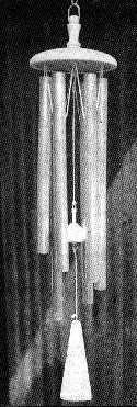
With the vane finished all the pieces should be ready for assembly. The knob is glued into the cap with waterproof glue. The strings on the tubes are looped over the string retainer (see photograph) and this sub-assembly is fixed with three screws into the recess on the underside of the cap. Finally the striker and the vane are attached with two strings. The vane should hang just below the bottom of the longest tube.
© Brian Clifford (August 1999)
|